
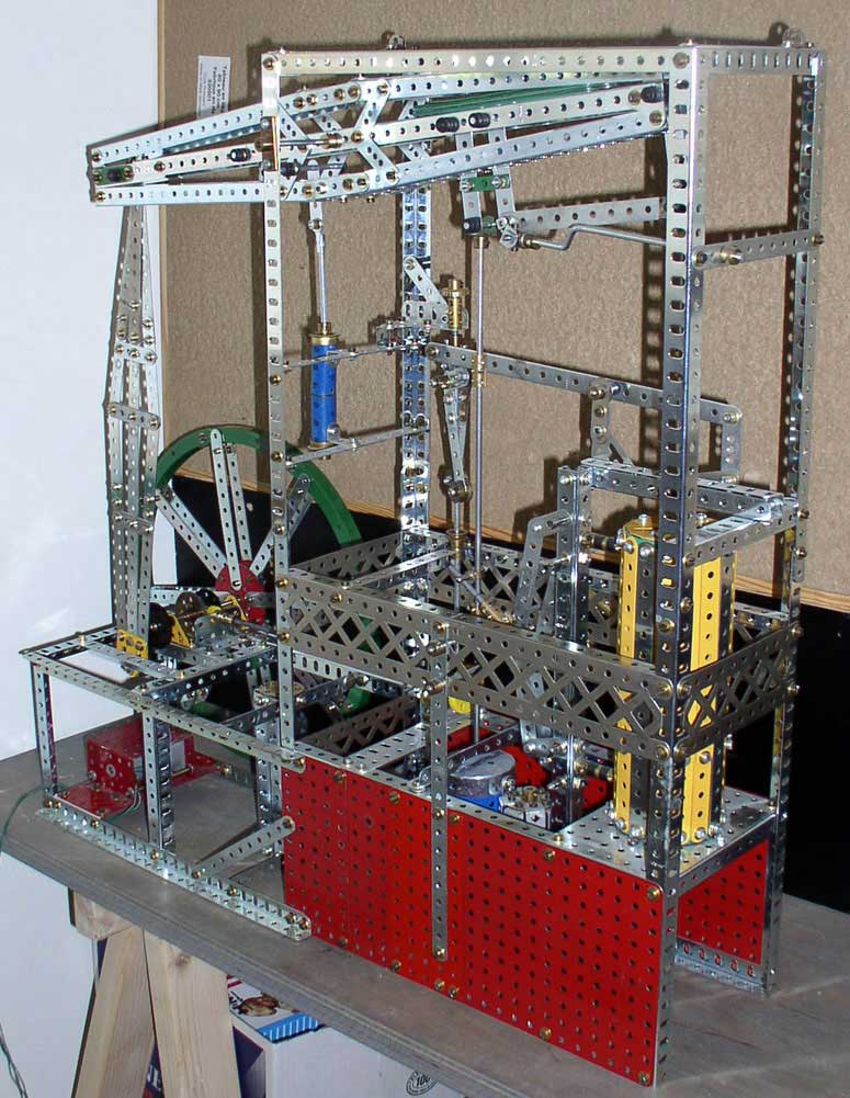
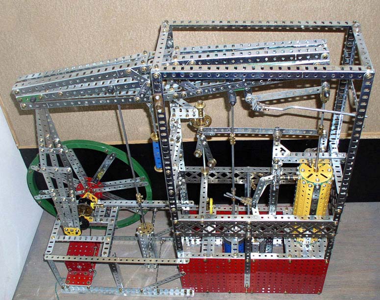
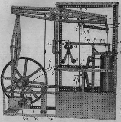
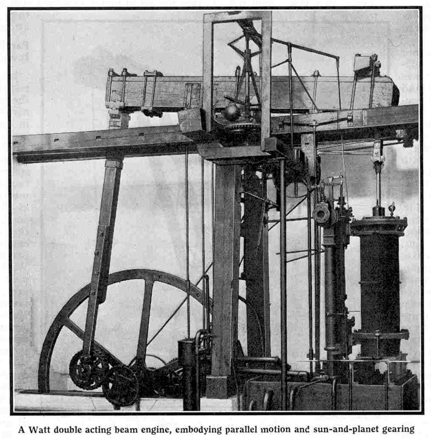
This model, Watt's Beam Engine 6.53 was first published in the 1930 4 - 7 instruction manual (illustration shown on the left) and is a model of the Boulton Watt double acting beam engine. The engine was a huge improvement on previous steam engines and used Watt's patented parallel motion. The model also demonstrates the sun and planet gear, the steam governor and water cooled condenser. Watt had used the sun and planet gear in the mistaken belief that the crank arm was patented. Later Boulton Watt engines employed a conventional crank arm. (See my other beam engine models) A very similar engine to this Watt's Beam Engine 6.53 built in 1785 is on display at The Power House museum in Sydney Australia and is quite possibly the prototype on which the Meccano model is based. Although James Watt did not invent the steam engine he made vast improvements to its power and efficiency. I built the model using modern zinc parts, red plates and nickel finished braced girders. The braced girders were not on the original manual design but were in the 1930 No. 6 set from which the model could be built, that I think give the model a nice period feel. Below is an interesting photograph of a Watt's Beam Engine published in the July 1927 Meccano Magazine possibly the inspiration of the Meccano model.
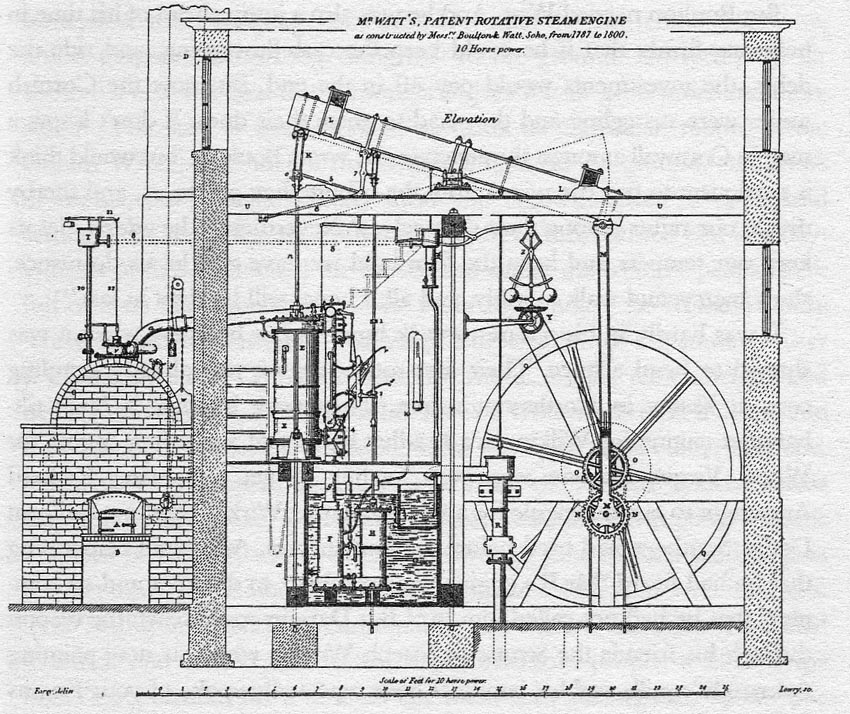
Below is a contemporary engraving of the Boulton Watt engine.
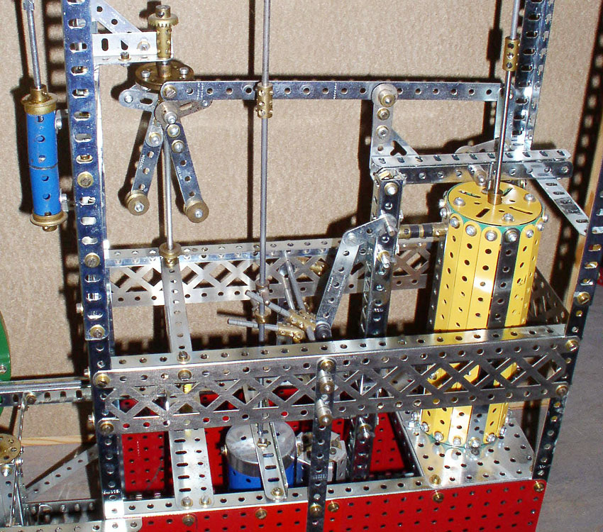
I have modified the crank arm to be able to make the fixed 57 tooth gear on the sun and planet gear more stable, partly because the original construction is not clear on the illustration in the manual. The use of plastic 57 tooth gears with a wider face is also a good idea. Several areas needed extra bracing and strengthening. Eleven hole double angle strips were far too short for the cross bracing. The cylinder construction was only hinted at with a list of additional parts required including flat girders, it was a lot easier to roll a couple of strips to make the inside frames. The tappet valves were returned using tension springs on the original model I could not get these to work in a satisfactory way so used counter weights (p/n 63). When everything is correctly aligned hardly any power is required to make it turn. The model was a joy to build and runs well driven by a low geared 6 volt bull motor and was in continuous operation at a local museum for an entire day. The Bull motor is no longer on sale but almost any other motor could be used with appropriate gearing if necessary. Page revised April 17 2021
|
.![]()