
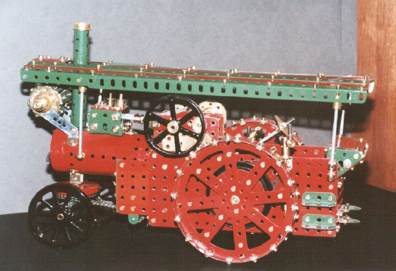
The main difference between this and the original (shown below) is in the use of flexible plates for the canopy these parts were not available when the plans were originally published .. The model is powered by an E20 electric motor c1957, a newer version of that used in 1928. The model is much better proportioned than many later models published by Meccano of traction engines these were often ungainly and ill proportioned one of the worst being the 1954 number ten model of a traction engine. The picture of the boy being hauled along is thought to be an office boy in the Meccano publicity department not quite sure how the standard Meccano rods and spoked wheels would have stood up to his weight though!
Jacques Vuye of France has also built the same model and has made some very significant improvements to the drive. These are described in the text and picture below. Differential for Meccano Steam Traction engine Supermodelby Jacques Vuye Overview The proposed mechanism provides a significant improvement to the operation of the Meccano Traction Engine Supermodel. The original design calls for a rigid axle with both traction wheels locked onto the rear axle. This results in poor turning capabilities for the model, mainly because most of the weight is concentrated on the rear wheels. The proposed improvement is based on Bert Love's differential described in his Meccano Constructor's book, but, in order to reduce overall width, it uses a toothed ring (#180) instead of a 133 teeth gear wheel (#27b). This allows assembly of the differential components inside the ring, instead of on top of the 133t gear wheel. The proposed mechanism adds less than 1" to the overall width of the model and has no significant impact on the otherwise pleasing proportions of the model. Assembly Begin construction by temporarily installing a 95t gear wheel (#27c) inside the Gear Ring (1). This will be used as a centring jig for the initial assembly. It is best kept in place using fishplates, temporarily bolted on both sides of the gear ring. Use any of the elongated holes for this purpose and reserve the circular holes for mounting the spokes of the differential later on Lock a short rod (e.g. 4") in the 95t gear wheel's boss. Install 4 long threaded pins (3) on a 4 holes collar (2) using locknuts. The threaded pins should be mounted in such a way that the collar runs freely on the centering rod. Install 4 short rod couplings (4) on each of the threaded pins, but do not lock the grub screws yet. Bolt the 4 short rod coupling (4) in the circular holes on the gear ring (1), using two washers as spacers and keeping the collar (2) on the centering rod. Lock the grub screws on each of the short couplings, while ensuring that the centering rod can turn quite freely in the boss of the 95t gear wheel and the collar (2). Now the collar and the differential "spine" are centred in the gear ring and the 95t gear wheel "jig" can be removed.
A large bevel gear is mounted on the right driving wheel and meshes with the bevel pinions in the same way as gear wheel (5). The proper shimming of the small pinion (6) is very critical, as they should not interfere with the nuts holding the bevel gear wheel (7) on the driving wheel. Washers are also used to adjust the space between bevel gear (7) and collar (2) When assembly is complete and proper meshing accomplished, a light coat of grease should be applied to the gears. Jacques Vuye 2000 Page revised May 05 2015
|
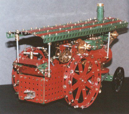 This is a model I built when I was really getting interested in Meccano again shortly after I bought a very little used number ten set from MW models. I built the model as close as possible to the original "Special instruction Leaflet" Super Model No. 22 Meccano Traction Engine.
The plans were originally published in 1928 when traction engines were a common sight for "Meccano Boys"
This is a model I built when I was really getting interested in Meccano again shortly after I bought a very little used number ten set from MW models. I built the model as close as possible to the original "Special instruction Leaflet" Super Model No. 22 Meccano Traction Engine.
The plans were originally published in 1928 when traction engines were a common sight for "Meccano Boys" 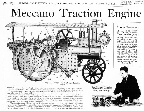
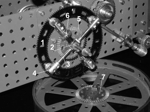 One of the threaded pins is now removed, making sure the three others remain undisturbed (as to preserve the perfect centering of
the collar (2)). Mount a small bevel gear (6) on the threaded pin, using a number of washers (including regular ones and Elektrikit
thin washers as well) for proper shimming. Mount the large bevel gear (5) on a short rod and insert in the collar (2). A number of
washers are inserted between gear (5) and the collar (2) to ensure smooth meshing of the pinion. Patience is required, as it will
usually take several attempts to achieve perfectly smooth operation.
One of the threaded pins is now removed, making sure the three others remain undisturbed (as to preserve the perfect centering of
the collar (2)). Mount a small bevel gear (6) on the threaded pin, using a number of washers (including regular ones and Elektrikit
thin washers as well) for proper shimming. Mount the large bevel gear (5) on a short rod and insert in the collar (2). A number of
washers are inserted between gear (5) and the collar (2) to ensure smooth meshing of the pinion. Patience is required, as it will
usually take several attempts to achieve perfectly smooth operation.