|
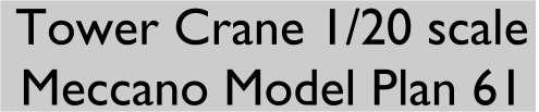
This 1/20 scale model is built from Model Plans 61, designed by Philip
Webb and originally published by MW Models in 1988. It depicts a
typical building site crane seen in towns and cities throughout the
world. Good use is made of braced girders, in fact twenty
six in total are required. I have used yellow and zinc parts, the
yellow is a mixture of Binns Road crane yellow and more recent French
yellow. The model is a joy to build and operate and at over 1.3
metres high and nearly 1.5 metres long its a good size to impress
but not
too big to be a problem transporting it around. When displayed at an exhibition on a table I was able to slew the boom round
above peoples heads, providing the load was near the tower. The
crane can be easily made smaller or larger dependant on your
availability of braced girders.
The mast and boom rotate on a vertical thrust bearing
consisting of a Meccano ball resting in a socket coupling. The side
bearing at the top of the tower consists of a wheel flange running
between plastic spacers. In the original model 0.5" plastic pulleys
were used but I found these gave two much slop, no doubt due to my
slight differences in construction from the original when building the
tower. I
repositioned the supporting rods and found that the plastic spacers
made a
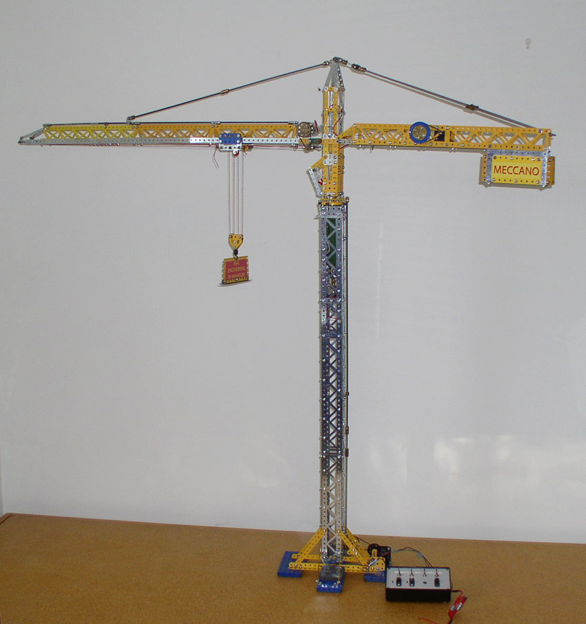
perfect fit. The top part of the model can be seen in the
pictures above and below. There are three motors used one for each of the
operations, slewing, hoisting and the trolley. I used two small French
Meccano 6 volt motors and a 12 volt Escap geared motor, for each of
these functions. The model uses a common earth wiring system
enabling just two wires to be threaded up through the thrust bearing.
The model is controlled by a 12 volt model railway controller and
on/off toggle switches mounted on the crane base. The wires to the mast and boom were connected using a small push together plug of the type used in R/C models, this facilitated easy assembly and dismantling.
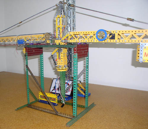 A few minor changes were made to Philip's original design.
Including the use of the small push on
rubber stopper/pulley p/n 23c (a part not available in 1988) on the
drive shaft
for trolley cord rather than just wrapping the string around the
shaft. I found the original method tended to slip and bind.
I beefed up the trolley construction using flat girders. I found that I
needed extra weight on the pulley block and substituted plastic 0.5"
pulleys with brass ones. I did not have a" Meccano Space" clear canopy
so
I constructed the cab front using narrow strips and transparent plates.
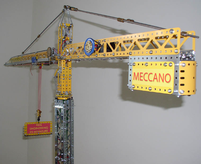
Picture 3 shows a close up of the control switches and the slewing
drive. Note the use of lead weights on the base to stabilize the crane A few minor changes were made to Philip's original design.
Including the use of the small push on
rubber stopper/pulley p/n 23c (a part not available in 1988) on the
drive shaft
for trolley cord rather than just wrapping the string around the
shaft. I found the original method tended to slip and bind.
I beefed up the trolley construction using flat girders. I found that I
needed extra weight on the pulley block and substituted plastic 0.5"
pulleys with brass ones. I did not have a" Meccano Space" clear canopy
so
I constructed the cab front using narrow strips and transparent plates.
Picture 3 shows a close up of the control switches and the slewing
drive. Note the use of lead weights on the base to stabilize the crane
The top picture shows three Liebheer tower cranes at a
construction site in Vancouver near Canada Place. The picture was taken
on August 30 2006. You can see how closely the model represents an
actual crane.
The plans to build this, model plan 61 & new version, Model plan 192 are available from Meccano Worldwide Mail
Order
The lower picture also shows the booms sitting in the cradle that I made to transport the model to exhibitions.
December 15 2005
Revised February 09 2015
|