![]()
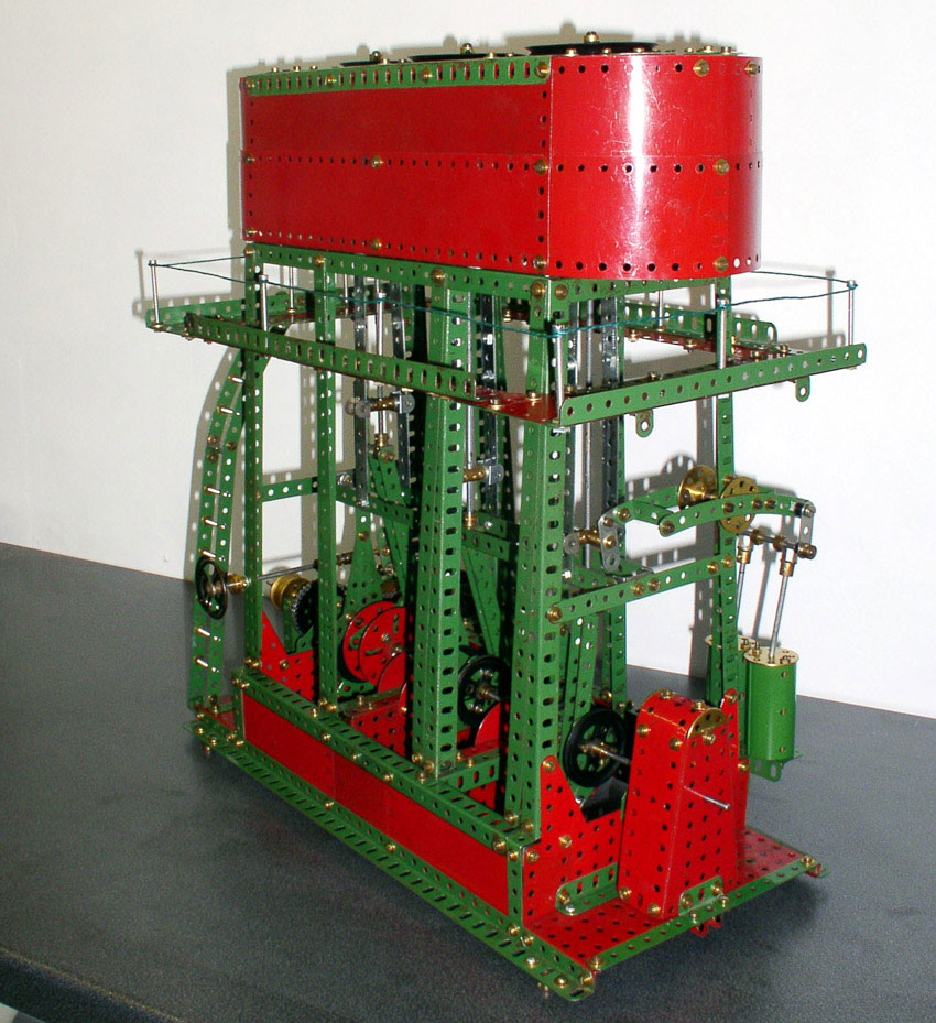
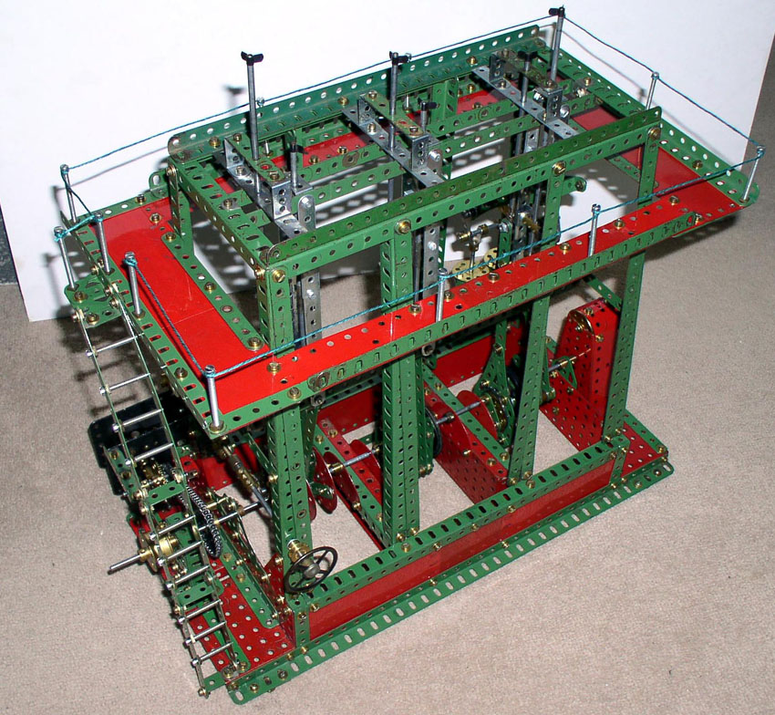
The model was built after I bought a collection of Meccano including a nineteen fifties Number 9 set, in February 2007. The model has three cranks, three built up eccentrics and two feed pumps, a nice feature is the screw operated valve that operates the E20R motor. One of the crucial factors with Meccano crankshafts is alignment and this is best done by initially only tightening up the bearings finger tight, until every thing is turning freely. Selecting true rods and square bosses is also crucial. Several improvements could easily have been made to the engine given more thought and better utilization of the parts supplied in the number 9 set of 1954. I did start out with every intention of building the model exactly as the plans but it became apparent at an early stage the small improvements would greatly enhance the model by using just a few additional parts. The 9 set would have been greatly improved by a few more angle girders and collars and a pair of 5.5" ring girders rather than the single one supplied. On the four central supporting pillars I used a pair of 25 hole angle girders rather than the 25 hole strip and single 25 hole angle girder to give the same solid appearance as those at each end. Another problem I found was the alignment and centralization of the frame supporting the the guides, see below for details. I used a second circular girder to form the frame of the cylinder casing this being 11 holes wide the same width as the built up ungainly looking method used in the manual and an obvious solution in model building terms. I have in addition used long non Meccano bolts for steps on the ladder and stanchions for the handrail round the cylinder head. I think this a solid looking and well proportioned model and looks very good in red and green too. I could have made further improvements but I did not to move too far from the original design.
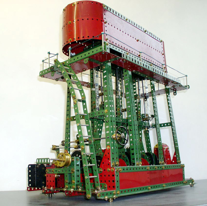
The picture at bottom of the page shows the engine before the cylinder casing was fitted. This would have been better done before fitting the inspection platform as it was impossible to hold the nut in each corner to do this I had to resort to a piece of masking tape to hold the nut behind the end hole. The picture also shows the alignment and centralization of the frame supporting the the guides for the piston rods and their vertical alignment with the top of the frame. This I found needed spacing out horizontally lengthwise using long bolts and fish plates. At the top on the width a hole was needed between the two hole spacing for the piston rod. This was easily solved using a modern two hole double bracket with a third central hole a part not in the number 9 set nor available at the time. The spring clips are to stop the rods dropping out if adjustments are needed to the crankshaft.
|
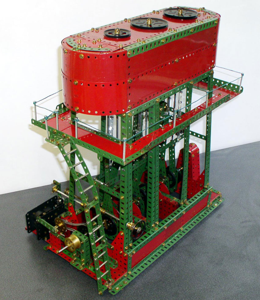
 This model of a marine engine" is from the 1954 number 9 instruction manual and depicts a "Triple Expansion" engine. Marine engines were always popular subjects for Meccano models in both Manuals and the Meccano Magazine. (Also see my model
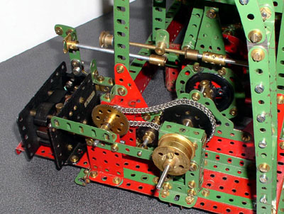 The original model and this were both powered by the E20R motor shown on the left but to preserve my 1958 vintage motor I replaced this with a modern motor. The picture below shows the new 12 volt
motor built into a frame with similar dimensions to that of the Meccano E20R following the
design of the late Norm LaCroix. The reduction gears are 19 tooth pinion / 57 tooth gear and a worm / 57 tooth gear directly driving the crankshaft. This eliminated the chain drive and made for much smoother running and the model easily ran for hours on end when exhibited.
The original model and this were both powered by the E20R motor shown on the left but to preserve my 1958 vintage motor I replaced this with a modern motor. The picture below shows the new 12 volt
motor built into a frame with similar dimensions to that of the Meccano E20R following the
design of the late Norm LaCroix. The reduction gears are 19 tooth pinion / 57 tooth gear and a worm / 57 tooth gear directly driving the crankshaft. This eliminated the chain drive and made for much smoother running and the model easily ran for hours on end when exhibited. 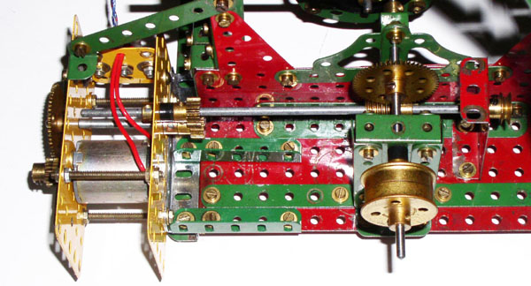
June 28 2007 Revised January 21 2021
![]()