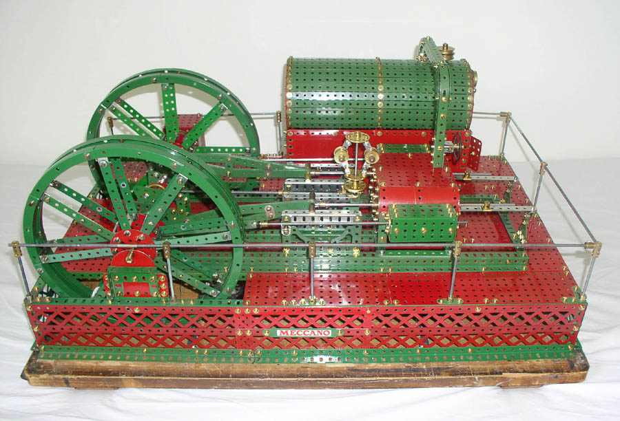
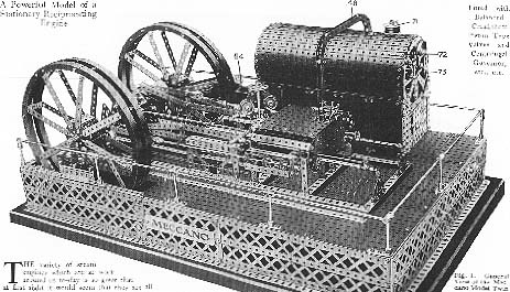
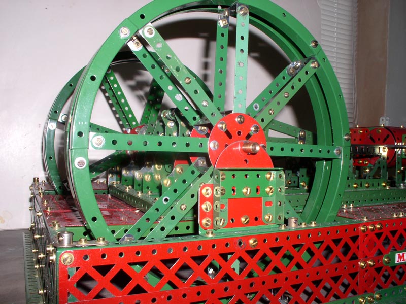
The instructions for this model were first published by Meccano Ltd. as Super Model Leaflet (SML) no.32 in 1929. A scan from original instructions shown on the left. I wanted to build this model ever since I bought "The Meccano Super Models " published by New Cavendish and written by Geoff Wright over thirty years ago. At the time I had no where near enough parts required to build such a large model. The model calls for a large range of perforated plates and braced girders but a bigger problem was the non availability of the Channel Segments P/N 119. This part was discontinued by Meccano in the 1935, 32 are required for the rims of the two flywheels. I very much wanted to use the Channel Segments as these give the flywheels a more elegant appearance than the large flange rings p/n 167b suggested as a replacement by the Meccano Company when part number 119 was discontinued. Replicas have been made since, notably by the late William R.(Bill) Inglis* from Australia, during the 1970s and sold widely. Unfortunately these were also discontinued. Late in his life Bill made a final batch and I managed to acquire from him the 32 required and had them powder coated in 1950s mid-green. So a long cherished ambition could then be fulfilled and construction begin. Some dealers such as Meccano Hobby.co.uk sell complete replica rings.
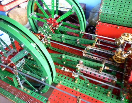
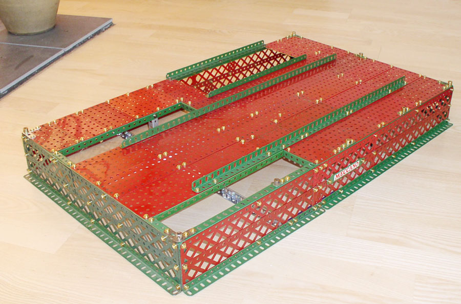
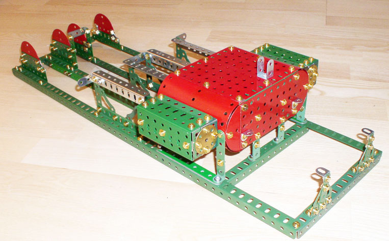
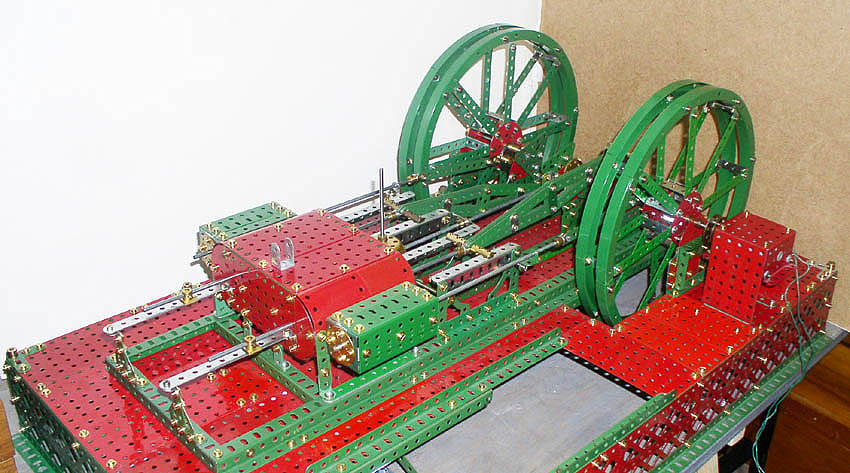
The pictures below show the various stages of
construction and the time spent on construction One riddle of the construction for me was the 9 hole strips
for the piston slides in front of the cylinders.The throw of the cranks was just to long for the
slide not hit the bolts at each end, I overcame this by making a ten
hole strip. Another builder has since told me he never came across this problem I imagine my problem was probably not closing up enough on the slotted holes. Many of the rods also needed to be of non standard
lengths, this was not mentioned in the instructions. Although filing
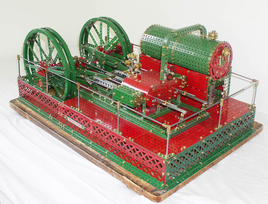
flats on the crankshaft rods was suggested but I did not find I needed to do this. . The model is driven through a belt reduction drive from a 12 volt non Meccano motor from a power tool.
A video of the engine made in January 2015 can be viewed on YouTube click on the logo.
A video of the engine running at the Museum of power Langford can be viewed on YouTube click on the logo.
|

 I have modified the design in several ways:-
Page created August 2004 Page last revised July 01 2019
![]()