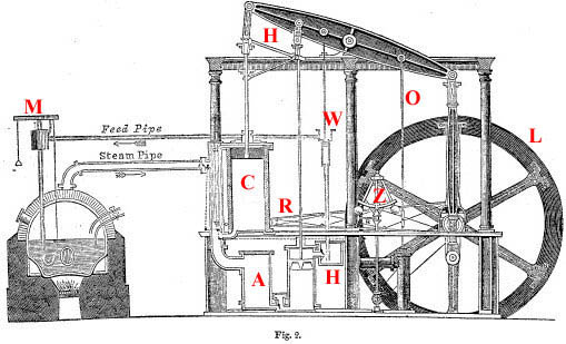
In 1765 Watt conceived the idea of a separate condensation chamber (A) , connected to the main one. This greatly improved the efficiency of the engine. Further developments raised the possibility of reciprocating engine development. An arrangement of valves (B ) could admit steam to either end of the main cylinder. (C) Consequently, the direction of the power stroke might be reversed. The resulting double action by the steam both pushing and pulling gave a very even movement to the piston. Before the development of the double acting piston, the linkage to the beam and the piston rod had been by means of a chain, which meant that power could only be applied in one direction, pulling. This was effective in engines that were used for pumping water, but the double action was not possible as long as the beam and the rod were connected by a chain, because while the rod moved vertically in a straight line, the beam was pivoted at its centre, with each side inscribing an arc. To overcome this Watt developed his parallel motion (D) . This masterpiece of engineering uses a four bar linkage in the form of apantograph to produce the required straight line motion. This meant that is was possible to use the motion of the beam to turn a wheel. This lead to the engine being known as a rotative steam engine. The most simple solution to transforming the action of the beam into a rotating motion was to connect the beam to a wheel by a crank, but because of perceived patent rights on the use of the crank, Watt was obliged to come up with another solution, the sun and planet motion and only later reverting to a crank. The crank (E) was attached to a heavy fly wheel (F) which, by its momentum maintained a constant power and smoothed the action of the alternating strokes. To its rotating central shaft, belts and gears could be attached to drive a great variety of machinery. Because factory machinery needed to operate at a constant speed, Watt linked a steam regulator valve to a centrifugal governor (G) . As a result of the improvements, Watt made the steam engine a truly practical machine that was able to replace the water wheel and horses as the main sources of power for British industry, thereby freeing it from geographical constraints and becoming one of the main drivers in the Industrial Revolution. By 1800 over 500 Boulton Watt engines were in use for both pumping water and driving machinery. Unfortunately James Watt did not develop the steam engine any further after it had reached what he considered a “state of perfection” and instead spent many years on litigation against those whom he considered had infringed his patents. Watt had considered and rejected the use of high pressure steam as dangerous and this also hindered for many years the development of a high pressure type of engine, the next logical step for steam power. A unit of power called the Watt was named after James Watt. Watt also coined the term “horsepower” to describe a unit of energy. Watt's innovations, coupled with the business acumen of his partner Matthew Boulton, made him very rich. Many of the massive beam engines built, to his design, for pumping water were still in use as late as the 1970s. KEY to illustration showing the main functions of the engine. (C) Cylinder (A) Condenser (H) Parallel Motion (R) Eccentric rod (L) Flywheel (M) Cistern (O) Cold water pump (W) Air Pump (H) Hot Well (Z) Governor The scan above is from the original encyclopedia engraving that inspired the model. The model can be seen in operation on YouTube click the link below.
|
 Although James Watt 1736 -1819 did not invent the steam engine he made many improvements and changes to the earlier Newcomen engine circa 1712. While Newcomen engines brought practical benefits, they were very inefficient in terms of the use of the energy to power ratio. The Newcomen steam engine used the force of atmospheric pressure to do the work. Thomas Newcomen's engine pumped steam into a cylinder, the steam was then condensed by cold water which created a vacuum on the inside of the cylinder. The resulting atmospheric pressure operated a piston, creating downward strokes.

![[*]](../images/bush.jpg) See also Watt's
Beam engine
See also Watt's
Beam engine